Wyze IP Camera Reverse Engineering
Nashad Mohamed
College of Computing
Georgia Institute of Technology
Atlanta, Georgia, United States
Mahta Tavafoghi
College of Computing
Georgia Institute of Technology
Atlanta, Georgia, United States
Abstract—This paper details the the current research found by
the Wyze Camera team in the Embedded Systems Cybersecurity
VIP. The team is focused on the sensor firmware of the Wyze
camera. Our objective is to understand the program and search
for vulnerabilities by reverse engineering the main program
binary files of the Wyze camera. This team aims to study the
Over the Air (OTA) protocol of the Wyze camera which will
lay the foundation for a RF fuzzing test bed which is the
technique in which malformed,invalid, or unexpected data is
fed into computer programs. Monitoring the program’s output
while fuzzing helps find crashes, memory leaks, and other issues,
which would present a way to discover security flaws in the Wyze
Camera.
I. BACKGROUND
An embedded system is a combination of hardware and
software that has been built to solve a few very specific prob-
lems[5]. Examples include automobiles, security and surveil-
lance systems, smart home devices, home appliances, elevator
controls, etc. They frequently have wireless capabilities[6].
Embedded systems can be designed to utilize an integrated
circuit (IC) or and operating system (OS). A system that
uses an IC is designed to operate on a specific hardware
platform[7]. Some embedded systems like Wyze IP Camera
run an operating system. The Wyze Camera V2 is an Internet
of Things (IoT) Device. It allows for wireless connection to
multiple devices, such as cameras, motion sensors, and contact
sensors, that together provide the user with surveillance over
many locations. When placed on a door or a window, contact
sensors tell users if the object they are placed on is open or
closed. Motion sensors add to detection capabilities and when
triggered, can even serve as precursor events to some- thing
coming into the camera’s view The ”Wyze - Make your Home
Smarter” mobile application provides real-time status updates
for the locations under surveillance by these devices.
With an increase in the use of wireless cameras the need for
enhanced security has also increased. In addition to widespread
use, risk is another component that drives security needs. Com-
panies need to perform security risk assessments to protect the
company from any future risks. The goal of the company is to
pinpoint any possible security breaches before the product is
used by the public. The risk assessment should review and
test systems and people for any vulnerabilities. There are
4 simple steps that are often utilized when implementing a
successful security risk management model. Firstly, identify all
sensitive data that is created, stored, or transmitted. Secondly,
an assessment should be preformed to pinpoint any security
risks. Thirdly, a mitigation approach needs to be found to
reduce the security risks. Lastly, a prevention method needs
to be implemented in order to protect data from threats and
vulnerabilities [11]. Many companies that produce IoT devices
have failed to prioritize security testing of these products,
leading to problems after production has already occurred.
In 2019, Wyze had a breach of data, leaving the personal
information of 2.4 million people exposed. It was reported
that from December 4th to December 27th, customers’ camera
information, email addresses, and Wi-Fi network details were
leaked [1]. The breach was detected by Twelve Security,
a consulting firm focused on protecting information, who
reported this as the most serious breach that they had seen
so far. For over three years, the Wyze camera has had security
flaws and vulnerabilities that have not been addressed by the
company such as the user name and email of those who
purchased and connected the camera to their home, emails
of any user a customer shared camera access with, and a
list of all cameras and nicknames for each camera [8]. This
allowed hackers to access stored video data and personal
information. Although Wyze has made some efforts to secure
devices, they have failed to make it a priority by discontinuing
their original WyzeCam without a proper explanation [9], but
vulnerabilities still exist in their products. These vulnerabilities
include, authentication bypass, remote control execution flaw
caused by a stack-based buffer overflow, and unauthenticated
access to contents of the SD card [10].
The ultimate goal of the team is to reverse engineer the Over
the Air (OTA) protocol in the Wyze camera, which will allow
the construction of a fuzzing test bed. Fuzzing is a software
testing method that reveals any software vulnerabilities or
defects by feeding invalid, malformed, or unexpected values
into a system [12]. Through over-the-air (OTA) packets, the
camera and dongle can communicate with each other. After
reviewing the OTA protocol, we can see the communication
channels and logs that reveal details about the metadata of the
camera, sensors, and other associated Wyze system devices.
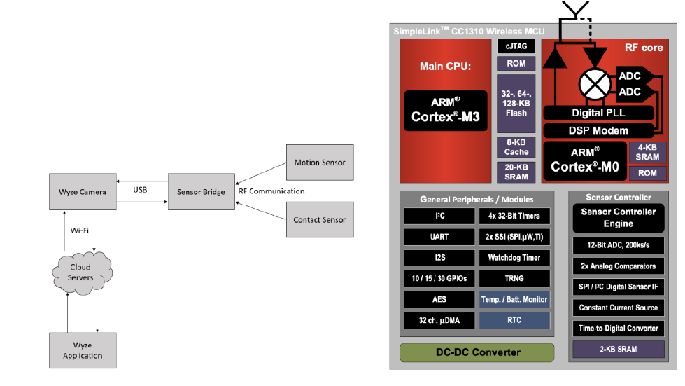
II. FUNCTIONAL DESCRIPTION
The Wype IP Camera V2 is made up of contact and motion
sensors, a sensor bridge, the camera itself, and the Wyze
application. The sensors and sensor bridge exchange
information through radio frequency (RF) communication.
The sensor bridge then transmits that information to the
camera through a USB connection. Wi-Fi connects the
camera to the cloud servers, so the information is then
transmitted to the Wyze app.
A. Sensor Bridge
The sensor bridge wirelessly links the motion and contact
sensor to the Wyze camera. The RF packet transmission and
reception is performed by the CC1310 micro controller, which
is responsible for controlling the sensor application code and
messaging logic.[3]
B. CC1310 Micro controller
The sensor bridge for Wyze camera is powered by the
CC1310 T1 Simplelink Wireless MCU. The image above
displays the CC1310 functional block diagram. The main
CPU in the CC1310 Wireless MCU is the ARM Cortex-M3,
which handles the application layer and protocol stack. The
ARM Cortex-M0 processor is in charge of handling all
low-level radio control and processing. It can be found in
the RF core. There RF core interacts with the main CPU,
which can be used to uncover information about how data is
arranged in the communicated packets. [3]
III. PREVIOUS RESEARCH
The team’s previous research began with finding vulner-
abilities that could expose sensitive information if they are
exploited. These vulnerabilities were that the Wyze camera
was susceptible to replay attacks and had unsigned firmware.
They took previously captured packets from a contact and
motion sensor and replayed it to a dongle which is an alias for
the Wyze sensor bridge. The sensor bridge is a hub that allows
the sensor to connect to internet. The previously captured
packets were replayed to the dongle using an USRP N210
which is a software defined radio used for RF applications
which was used by the team to transmit and receive RF signals.
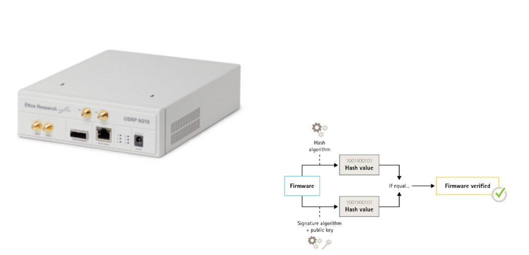
Figure 5: The image above displays the USRP N210 that
was used to transmit and receive RF signals.
The packets were received successfully by the dongle as veri-
fied by the input shown in the Wyze application. Unfortunately
this meant that the dongle was not properly checking if it
was receiving a previously received message and therefore
vulnerable to replay attacks. The initial packet linked to an
alert features a 4-digit hexadecimal value that increases with
each alert but resets when the sensor loses power. When
captured packets were played back, this 4-character field
reverted to the captured value. Although the meaning of these
4-characters is unknown, their incremental behavior during
event occurrences (such as open/close or motion/no motion)
suggests they may serve as a sequence counter. This 16-bit
sequence counter increases each time an event occurs and
resets to 0 when the sensor loses power. The dongle can
process recorded packets in any order as long as the event
types alternate between open and closed.
In embedded systems, the creators of the firmware have the
option of signing their firmware which prevents the firmware
from being modified, changed, or corrupted and flashed onto
a device. Signing firmware is implemented when the creator
signs the firmware with a private key. After it has been signed,
the device will validate the the firmware before allowing
an installs to take place. If the device detects that any of
the firmware’s integrity is compromised, the install will be
rejected. The first step in the firmware signing process involves
calculating a cryptographic hash value, which is then used to
sign the firmware image with the private key of a public/private
key pair. When upgrading firmware, it is important to verify
the integrity of the new firmware by using the public key
to confirm that the hash value was signed with the corre-
sponding private key. Additionally, the firmware’s integrity
can be verified by computing its hash value and comparing
it to the validated hash value obtained from the signature
[14]. This process of signing firmware is done by having the
firmware securely signed by the signing server. After this,
it travels through the supply chain and reaches the device.
The device then verifies the signer’s digital signature and
if this is successful, the platform installs and executes the
firmware. Otherwise it fails due to an incorrect key being used
or the signature/firmware was modified. This firmware signing
is very critical for protecting the firmware. The firmware
on the devices of the Wyze system is not signed, allowing
unauthorized firmware to be flashed onto the devices [15].
Figure 4: Process of signing firmware
The team also observed communication during startup and
movement in front of the camera and sensors. From this they
gathered log files for many different communication scenarios
between the sensor and sensor bridge. This gave them the
opportunity to observe the different device communication
transmissions. After looking at the real time streaming protocol
(RTSP) log files they discovered that there were certain parts
of the communication that directly matched with the packet
information.
Previous research was focused on parsing functions involv-
ing communication between the CPU and Radio. There has
been some research done outside of the team where someone
unpacked the camera’s firmware and disassembled the code
to understand the how the communication works between the
camera and the dongle [17]. Reverse engineering was done
to Wyze’s proprietary RF protocol between touch sensors, the
motion sensor and the sensor bridge. The team also analyzed
Over-The-Air captures of records between the sensor bridge
and the sensors. Some of the vulnerabilities that still exist are
replay attacks and unsigned firmware.
IV. CURRENT RESEARCH
A. Using Ghidra to Reverse Engineer Wyze firmware
Ghidra is an open source software developed by the Na-
tional Security Agency (NSA). To reverse engineer the Wyze
Camera’s firmware, Ghidra was utilized [4]. A TI debugger
was utilized to transfer all of the memory of the Wyze camera
into binary files. This allowed for the firmware of the camera
to be obtained, in addition to other information like the
SRAM. The binary files are disassembled through Ghidra into
assembly instructions, which can be decompiled further into
pseudo source code. Since Ghidra does not have knowledge on
structures, registers, and regions, the System View Description
(SVD) loader is used, as it generates structures and memory
maps automatically. [13] To understand transmit and receive
command structures, which allow for RF signals to be trans-
mitted and received, within the Ghidra code, the CC13x0,
CC26x0 SimpleLink™ Wireless MCU Technical Reference
Manual by Texas Instruments is referenced [2]. The manual
contains information on the RF protocol and the transit and
receive command, which will be helpful in understanding the
camera binary files.
B. Radio Frequency (RF) Command Structures
The RX ADV and TX ADV structures were located us-
ing a scalar search of their command numbers in the don-
gle binary. When looking at the binary files in Ghidra,
it can be observed that there are RF structures in the
code that are used by the radio to transmit and receive
packets. This includes the rfc CMD PROP RX ADV t and
rfc CMD PROP TX ADV t structures. The CC1310 Techni-
cal Reference Manual defines these command structures and
gives meaning to the byte and bit fields. The information
gathered from the structures will be used to interpret the
packets being received from the system.
C. Advanced Packets
It was discovered that the Wyze system utilizes advanced
packets for communication. This was proven by using a scalar
search on the binary to locate the command numbers for
transmitting and receiving. Using the CC1310 MCU SDK, the
standard packets command numbers are 0x3801 x3802, and
advanced packets command numbers are 0x3803 and 0x3804.
The scalar search showed that only the command numbers
of the advanced packets were in the Wyze binary files. This
ultimately led to the conclusion that the Wyze system utilizes
advanced packets. [3]
D. Transmit Command Struct
The Transmit Command Structure focused on the
rfc CMD PROP TX ADV s structure which was found in
the 0.0.0.33.bin file. The rfc CMD PROP TX ADV s struc-
ture is one of the radio structures referenced in the code and
contains important information about the OTA protocol. This
command structure transmits a packet with the format shown
in figure 6. This structure is found in the 0.0.0.33.bin file that
is a part of a contiguous memory region in the SRAM that
the team examined using Ghidra. Ghidra displays this code
in assembly and its disassembled pseudo C code. The radio
must be set up in a compatible mode such as proprietary mode
(data received over the air is stored in a receive queue) and
must use CMD FS which is a radio operation command. The
packet starts at the given trigger iwth a fixed delay unless
startConf.bExtTXTrig (shown in figure 7) is 1, then the packet
transmission starts on an external trigger to the RF core.
The modem first transmits the preamble and sync word as
configured. If preTrigger is not TRIG NOW, the preamble
is repeated until that trigger is observed. If preTrigger is
TRIG NOW, the preamble is sent once and then the sync
word. The sync word to transmit is given in the syncWord
field. If numHdrBits is greater than 0, a header of numHdrBits
is sent next. The header is transmitted as one field in the bit
ordering programmed in the radio. If the header has more
than 8 bits, it is always read from the transmit buffer in little-
endian (stores the least-significant byte at the smallest address)
byte order. If the radio is configured t0 transmit the most
significant bit first, the last header byte from the TX buffer
is transmitted first. After the header, the remaining bytes in
the buffer pointed to by pPkt are transmitted. The payload is
then transmitted byte by byte, so after the header, no swapping
of bytes occurs regardless of bit ordering over the air. The total
number of bytes (including the header) in this buffer is given
by pktLen. A CRC can be calculated and transmitted at the
end if pktConf.bUseCrc is 1. Whitening can also be enabled.
The header may contain a length field or an address, and if
so, these fields must be inserted correctly in the packet buffer.
If pktLen is 0, unlimited length is used and pPkt points to a
transmit queue instead of a buffer.
The parameters for this structure are shown in figure 7.
The structure values that were of importance were bUseCRC
= 0x01, numHdrBits = 0x10, pktLen = 0x5, and pPkt =
DAT 200026bc. The packet being sent by the Advanced
Transmit Command Structure is held in a transmit buffer
pointed to by pPkt (pPkt is equal to the pointer DAT 20026bc).
When pktLen is 0 a queue is used rather than a buffer, but
in this case it is equal to 0x5. After following the pointer
DAT 200026bc in Ghidra, it took us to the transmit buffer
in memory show in figure 8. Since we knew the pktLen
was 0x5 we were able to figure out where the end of the
packet was. From here we could focus the reverse engineering
efforts on these XREFs to these memory locations. Since the
numHdrBits is 0x10 it was concluded that the header consisted
of the first two memory locations in the packet buffer which
have the value of 0x07 and 0x08 which is shown in figure 8.
The two header memory locations were being referenced by a
function called FUN 000106d0. We started our research here
this semester.
Figure 6: Advanced Packet Format
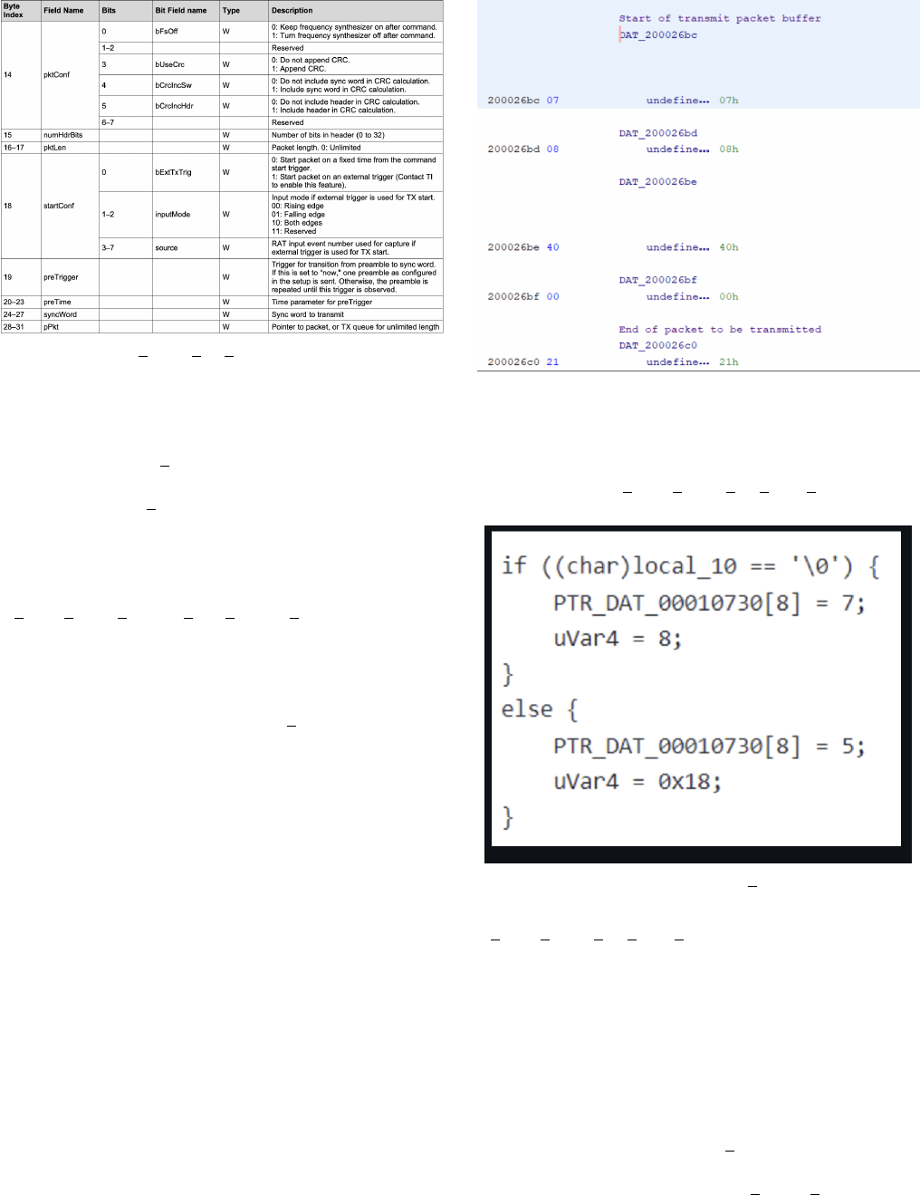
Figure 7: CMD PROP TX ADV Command Stucture
The function FUN 000106d0 assigns the header bytes
which is shown in figure 9. At first it looked like the function
was dependent local 10, but we did not find much to prove
that this was true. The header information was actually related
to the CRC. The radio was configured in IEEE 802.15.4g
mode which occurs when formatConf.whitenMode is set to
4, 5, 6, or 7. formatConf.whitenMode is a field from the
rfc CMD PROP RADIO DIV SETUP s structure. [16]. The
first 11 bits of the packet are set to the number of bytes in
the payload plus the number of bytes in the CRC.Since the
length of the packet are 5 bytes and the header is 2 bytes,
the payload consists of the remaining 3 bytes. Since the CRC
is 32 bits, its contribution to the ”total length” variable is 4
bytes [16]. The value ”7” was written to the first 11 bits of
the packet.
Some information we discovered from the technical manual
was that when formatConf.whitenMode is 5 or 7, the radio is
configured to produce the 32-bit CRC and whitening defined in
IEEE 802.15.4g. When formatConf.whitenMode is 6 or 7, the
radio also processes the headers in both transmit and receive
in the following way. If bit 15 of the header is 1, the frame is
assumed to consist of only a header, with no payload or CRC.
If bit 15 12 of the header is 1, the 16-bit CRC defined in IEEE
802.15.4g is assumed instead of the 32-bit CRC. For transmit,
2 is added the offset of the length to account for this. If bit 11
is 1, whitening is enabled, otherwise it is disabled. What we
gathered from this is that the header is set in a way that the
receiver of the packet can verify if the CRC is 16 or 32 bits
or if whitening is enabled. Another thing that was discovered
is that the else block is the case where the CRC is 16 bits
because the math lines up with total length 0x05. Also, the
12th bit would be 1 in this case.
Figure 8: Start of the transmit packet buffer
When analyzing this structure the most important step was
to examine the definition of each structure value and construct-
ing a table that had each description. The information that was
being sent by the rfc CMD PROP TX ADV s structure was
held in one of the important transmit buffer pointed by pPkt.
Figure 9: Function FUN 000106d0
The main takeaways from this function were that The
rfc CMD PROP TX ADV s contains a pointer pPkt that
points to a buffer where the packet to be transmitted resides,
the packet header contains information on the total length
of the packet (payload length plus CRC length), whitening,
and CRC length and the packet format is in accordance with
IEEE 802.15.4g format since the radio has been setup in the
appropriate mode.
E. 00002520
r
adio
s
omethingF unction
This is a function found in the 0.0.0.33.bin file. I found
it from following the pointer DAT 200026bc. It checked if a
variable that we do not currently know the meaning of equals
to 0x3401 or 0x3404. 0x3401 is PROP DONE RXTIMEOUT
which means that the operation stopped after end trigger
while waiting for sync. 0x3404 is PROP DONE STOPPED
which means the operation stopped after stop command. After
checking if the unknown variable equals one of these two
values, it stores the register byte with an offset of 0x02. It calls
two functions FUN 000525c which I tried to find its purpose
but I found that it was insignificant. It also called another
function called FUN 0000f21c which reversed the bits of the
packing using the modified length. It gets the packet length
from the first 11 bits of the packet header. Then it checks if
bit 12 of the header is 0 to find the length of the CRC of the
packet. Since bit 12 is 0, the CRC is 32 bits. Then it checks
bit 15 of the packet data to see if the frame contains data or
just a header. Since bit 15 is 0 there is data and CRC. This
function takes in a pointer to the third byte of the packet data
in the receive data queue and the modified value for packet
length. From bit 15 it checks of the length is less than than
the max length.
F. Receive Command Struct
In order to gather information about the receive command
structure, a similar approach was used to the transmit
command structure. The RX ADV command includes a
16-bit head with 11 bits belonging to the length field.
The rfc CMD PROP RX ADV t structure is stored in
the receive packet buffer, which is pointed to by the
pQueue. This is located in memory at the location 2003be8.
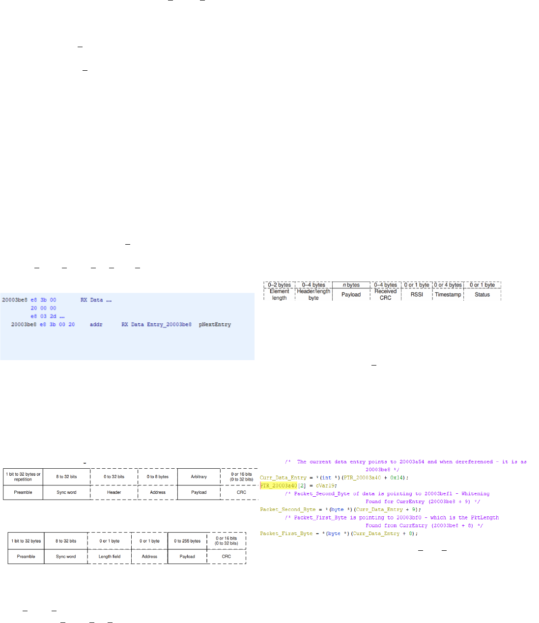
Figure 1: Location of the receive command struct in memory
G. Packet Contents
Previous research for this team found that the packets were
not encrypted and/or whitened. Using the TI SDK, information
about the physical structure of the packets was uncovered.
Figure 2: Standard Packet Format
Figure 3: Advanced Packet Format
This figure above highlights the differences between the
CMD PROP RX, which is used to receive a packet or packets,
and the CMD PROP RX ADV, which is used to receive
packet or packets with advanced modes. As shown in Figure
2 and 3, the preamble and sync word can hold the same
number of bits. However, the next field is different between
the packets. The advanced packet format for receive has the
capability to receive packets with a length byte that is greater
than 8 bits. Additionally, the length information does not have
to be at the beginning of the header.
H. RF Data Queue
In order to maintain packets transferred over the air, the
CC1310 utilizes a data queue. Data queues are responsible for
transferring a packet from the RF core to the main CPU, and
the other way. The data queue has a pointer that is labeled
as pQueue, which is a pointer to the current entry in the data
queue that is being processed. Additionally it is a pointer to
the last entry that was added to the data queue.[2] Data is
placed in the RX buffer when a packet is being received. [2]
If the pQueue is NULL, this means the packet is never stored.
Figure 11: Receive Buffer Entry Element
A general structure of a data queue entry is as follows shown
in the figure above. The RX ADV structure has was found to
have a 16 bit header, where 11 of the bits belong to the length
field. The rest of the bits in the header are padded, as they are
unused. N bytes (n - variable length) is the payload, 1 byte is
the RSSI, and 1 byte is the timestamp.
Figure : Code referencing Curr Data Entry
The current data entry is the pointer to the pQueue, which
points to 0x2000a54, which is 0x20003be8 when it is deref-
erenced. The current data entry is then used to find the first
and second bytes of the buffer.
Figure 10: Packet First Byte and Packet Second Byte
values
In the code above, the current data entry was added by 9, and
then dereferenced with gave 0x20003bef1, so this is where
the whitening is located, which is the packet second byte. The
packet first byte is the current data entry added with 8, which
is at 0x20003bf0. This is the packet length of the entry.
V. CONCLUSIONS
The team was focused on continuing to understand the RF
command structures, transmit and receive. We used Ghidra to
reverse engineer the Wyze Camera’s binary files by examining
assembly and disassembled pseudo C code that we deciphered
using the CC13x0, CC26x0 SimpleLink™ Wireless MCU
Texas Instruments Manual. We referenced the 0.0.0.33bin file
to make comments on code. We tried to understand how
the Wyze Camera was transmitting and receiving RF signals.
The goal moving forward is to get application data from the
payload to aid in making a spoofer/message encoder, and
eventually create a fuzzing test bed. We also want to continue
reverse engineering the sensor’s firmware to determine the RF
parameters that we need. We need to reverse engineer the IP
camera main program binary to find how wireless data is used
by the program and to search for vulnerabilities and determine
the application data of packets.
REFERENCES
[1] S.E. Garcia, ”Data Breach at Wyze Labs Exposes Infor-
mation of 2.4 Million Customers,” The New York Times,
https://www.nytimes.com/2019/12/30/business/wyze-security-camera-
breach, Dec. 31 2019
[2] T. Instruments, “Cc13x0, cc26x0 simplelink™ wireless mcu technical
reference manual,” Texas Instruments, Feb 2015.
[3] M. Dee, M. Yuan, T. Kapadia, and A. Verzino, “Wyze Camera Report,”
2022.
[4] “Home,” GitHub. https://github.com/NationalSecurityAgency/ghidra/wiki
[5] B. Daniel, “What Are Embedded Systems?,” www.trentonsystems.com,
Jul. 22, 2021. https://www.trentonsystems.com/blog/what-are-
embedded-systems
[6] B. Lutkevich, “embedded system,” IoT Agenda, 2020.
https://www.techtarget.com/iotagenda/definition/embedded-system
[7] “Integrated circuits vs Embedded systems: What’s the difference?,”
Oct. 23, 2022. https://www.icrfq.net/integrated-circuits-vs-embedded-
systems/What is an embedded system
[8] B. Lovejoy, “Wyze camera security breach: 2.4m users have per- sonal
data exposed.” https://9to5mac.com/2019/12/30/wyze-camera- security/,
Dec 2019
[9] B. Patterson, “Wave goodbye to the original Wyze Cam”
https://www.techhive.com/article/609060/wave-goodbye-to-the-original-
wyze-cam.html, Jan 2022
[10] Bitdefender, “Vulnerabilities Identified in Wyze Cam IoT Device”
https://www.bitdefender.com/blog/labs/vulnerabilities-identified-in-
wyze-cam-iot-device/, Mar 2022
[11] “What is Security Risk Assessment and How Does It Work? — Synop-
sys,” www.synopsys.com. https://www.synopsys.com/glossary/what-is-
security-risk-assessment.html: :text=A
[12] “What Is Fuzz Testing and How Does It Work? — Synop-
sys,” www.synopsys.com. https://www.synopsys.com/glossary/what-is-
fuzz-testing.html: :text=Fuzz
[13] “SVD-Loader for Ghidra: Simplifying bare-metal ARM reverse en-
gineering :: Security for the embedded and connected world,” level-
down.de, Sep. 13, 2019. https://leveldown.de/blog/svd-loader/
[14] Chipkin, “Signed Firmware” https://store.chipkin.com/articles/signed-
firmware: :text=What
[15] stacksmashing, “Iot security: Backdooring a smart
camera by creating a malicious firmware upgrade.”
https://www.youtube.com/watch?v=hV8W4o-Mu2ot=612s.
[16] T. Instruments, “Cc13x0, cc26x0 simplelinkTM wireless mcu technical
reference manual,” Texas Instruments, Feb 2015.
[17] hclxing, “My Not-So-Boring Life,”
https://hclxing.wordpress.com/2019/05/30/reverse-engineering-
wyzesense-bridge-protocol-part-ii/, May 2019.
